cc3D Openpilot Upgrade Version OPLink Revo - AEROBOT UAV Flight Systems Multicopter und Zubehör


cc3D Openpilot Upgrade Version OPLink Revo
Das OpenPilot Revolution Board, auch genannt "Revo", ist eine neue Generation von Autopilot (STM32F4 Serie, 210MIPS ARM Mikrocontroller). Inkl. FPU (floating point unit) , ein großer Fortschritt für Hobby-Autopiloten. 32bit seit dem ersten Tag und der FPU ist ein weiterer Schritt auf der Performance-Leiter. Das Revolution-Board ist ein Flugsteuerungscomputer mit Autopilot, für Multicopter, Hubschrauber und Motorflieger. Es ist ein Full-10DOF mit Gyroskop, Beschleunigungssensor, Magnetometer und Drucksensoren
Alle Softwareneuerungen werden in der englischen Dokumentation fortlaufend aktualisiert.
Da das Board sehr flexiebel ist und eine Viezahl an Einstellungsmöglichkeiten bietet, ist es nicht unbedingt für Neueinsteiger geeignet.
Die Bedienung erfodert eine Auseinandersetzung mir der Materie wie bei einer APM oder Pixhawk Steuerung.
Der Beschrieb des Herstellers:
CPU
•CPU is the STM32F405RGT6 chip, with ARM Cortex-M4 core at 210MIPS, FPU, and saturation arithmetics DSP functions.
•The chip features a range of built-in hardware modules that can be programmed once and function independently, requiring little to no CPU overhead. These include 14x multichanel timers, 3x synchronous-sampling ADC serving up to 24 channels, 2x DAC, matrix memory controller with 16-stream DMA, and other. Communication modules include USB2.0, 3x I2C, 3x SPI, 4x USART, 2x CAN and SIDO. All these modules can be configured for accessing the chip pins using a flexible switch matrix, or disabled to save power.
•It even contains a real time hardware calendar if you want a wake up flight.
•The software and settings are loaded through USB connector and no-hassle update function in the GCS (Ground Control Station).
Modem
•The board features a built-in 433MHz OPLink Modem.
Dimensions
•OpenPilot products use the standard OpenPilot footprint, and hence has the same dimensions and mounting holes as the OpenPilot CC. CC3D, Revo, GPS, OSD and PipX boards.
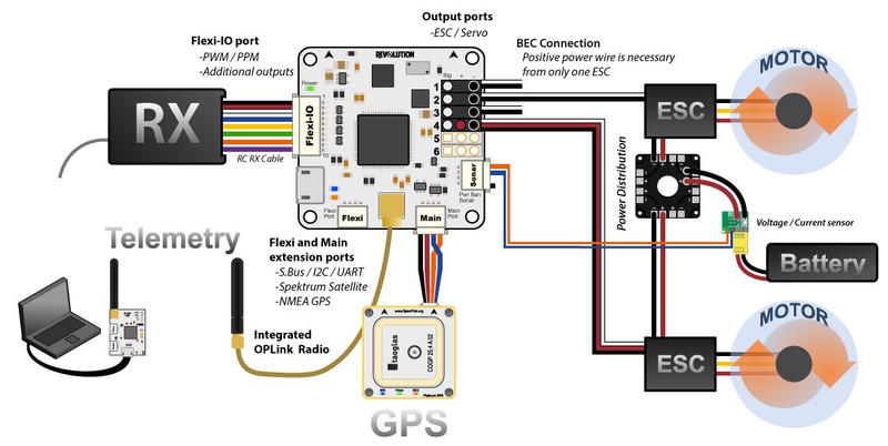
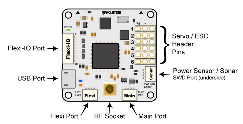
Ports
•Servo 1-6: These are the PWM outputs that go to servos or electronic speed controllers (ESCs). Power for the flight controller is typically supplied through these headers from only one of the ESCs, but in most cases, all the servo wires can be left connected. Cutting the pin from servo wires is highly discouraged. If you feel you must disconnect three of the hot wires, use some shrink tube or electrical tape to insulate the removed pin (you may need that positive voltage at a later date!). The positive (Vcc) and negative (Gnd) pins are indicated on this diagram and the board. In rare cases, you may need to also disconnect the ground pin if your ESCs are creating ground loop problems (indicated by a general weirdness in setup). (see the CopterControl - CC3D -Atom Hardware Setup page, Power section, for instructions on how to remove and insulate the extra pins)
•Servo output pin layout is:
- Outside --> ground
- Middle --> 5V - 8.4V
- Inside --> signal
•Flexi-IO Port: JST-SH 10-pin. The receiver port can act as an input or output port depending on the configuration which is set in the Hardware Settings. Configuring the receiver port as an output port allows the user to assign more output channels then the 6 standard servo outputs.
•PWM -vs- PPM Recievers
Please be aware that not all receivers can be configured to use a PPM output. It is the user's responsibility to research this feature in regards to the
desired receiver they wish to use for PPM and ensure it can be used as such. Many hours of frustration can occur while trying to troubleshoot why
you can't get your radio to connect to the board with PPM if using a receiver than isn't designed with that feature! Simply make sure the receiver can
do it before trying to set it up that way.
• MainPort: JST-SH 4-pin. This is a serial USART whose baud rate can be adjusted through the GCS. Optionally, Futaba S.Bus receiver, Spektrum/JR satellite receiver or GPS can be mapped to the MainPort. Default configuration is Telemetry for connecting an RF modem.
•FlexiPort: JST-SH 4-pin. The function of this port also depends on the configuration and can be configured for I2C or Serial. The default configuration doesn't use this port, but it can be used for Telemetry, GPS, Spektrum satellite receivers (all working), and other I2C peripherals (under development).
• RF Socket: Antenna connection socket for on-board OPLink modem.
• Pwr Sen/Sonar Port: JST-SH 4-pin. This port can be configured to accommodate an Autopilot current sensor and a low cost Sonar sensor such as the HC-SR04. It can also be used as a general purpose input/output port or as a one or two channel analog input port.
Please note that the output rate on the output channels from the Flexi-IO Port cannot be set individually. If servos are connected to this outputs, you must ensure that they can work with the defined output rate for the bound channel. E.g. if you choose a high output rate to support an octocopter configuration, the update rate from the output channels from the ReceiverPort are bound to the update rate from channels 5 & 6. In this case, you cannot connect analog servo's to these outputs since an analog servo only supports an output rate of 50Hz..
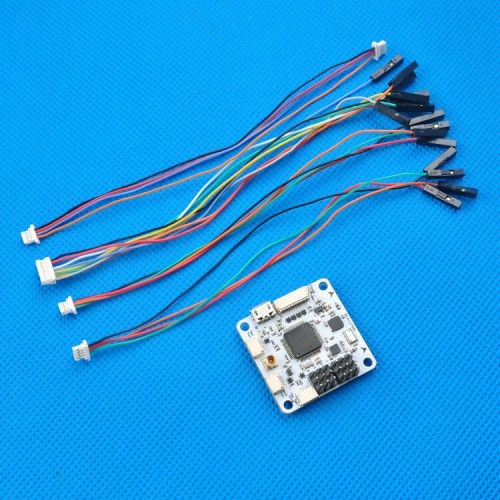
Lieferumfang:
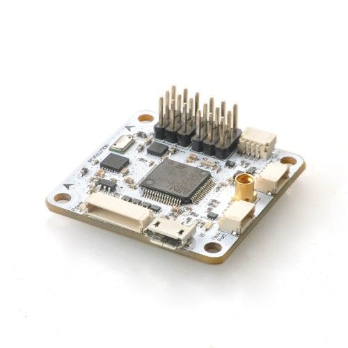
•cc3D Revo Flugkontroller
•Kabelsatz


